TECHNICAL REPORT 2
FOUNDATION
Introduction
Foundations provide support for
structures, transferring their load to layers of soil or
rock that have sufficient bearing capacity and suitable
settlement characteristics to support them.
There are a very wide range of
foundation types suitable for different applications, depending on
considerations such as:
- The nature of the load requiring support.
- Ground conditions.
- The presence of water.
- Space.
- Accessibility.
- Sensitivity to noise and vibration.
Very broadly, foundations can
be categorized as shallow foundations or deep foundations.
- Shallow foundations are typically used where the loads imposed by a structure are low relative to the bearing capacity of the surface soils.
- Deep foundations are necessary where the bearing capacity of the surface soils is not adequate to support the loads imposed by a structure and so those loads need to be transferred to deeper layers with higher bearing capacity.
Types of deep foundations
1.
Strip foundation (or footings)
Strip foundations are a type of
shallow foundation that are used to provide a continuous, level (or sometimes
stepped) strip of support to a linear structure such as a wall or
closely-spaced rows of columns built centrally above them.

Strip foundations can be used for
most subsoils, but are most suitable for soil which is of relatively good
bearing capacity. They are particularly suited to light structural loadings
such as those found in many low-to-medium rise domestic buildings - where mass
concrete strip foundations can be used. In other situations, reinforced
concrete may be required.
Generally, the size and position of
strip foundations is typically related to the wall’s overall width. The depth a
traditional strip foundation is generally equal to or greater than the overall
wall width, and the foundation width is generally three times the width of the
supported wall. This results in the load being transmitted at 45º from the wall
base to the soil.
The underside of strip foundations
should be deep enough to avoid frost action; for example, at least 450 mm
unless they are bearing on rock, and at least 1 m on high shrinkage clays.
Deep strip foundations may be
necessary where soil with a suitable bearing capacity is deeper.
Wide strip foundations may be
required where the soil is soft or of a low bearing capacity, so as to spread
the load over a larger area. Wide strip foundations will typically require
reinforcement.
2.
Pad foundations
Pad foundations are generally
shallow foundations, but can be deep depending on the ground conditions. They
are a form of spread foundation formed by rectangular, square, or sometimes
circular concrete ‘pads’ that support localised single-point loads such as
structural columns, groups of columns or framed structures. This load is then
spread by the pad to the bearing layer of soil or rock below. Pad foundations
can also be used to support ground beams.
They are generally of a uniform
thickness, but sometimes the upper face may be sloped or stepped. Their plan
shape will depend on the nature of the applied load and the allowable bearing
capacity of the layers below. Their thickness must be sufficient to distribute
the load across the plan shape. They are generally reinforced on all but the
smallest structures, with the reinforcement allowing higher loads to be imposed
and the construction of shallower pads which require less excavation and use
less concrete.
The arrangement of pad foundations
will vary depending on the nature of the structure they are supporting, the
loads imposed, the allowable bearing capacity of the layers below and the space
available on site. They may be:
a. Plain
concrete
Plain concrete pad foundations that
do not use reinforcement are an economical solution but only where the applied
load will be relatively light. These can also be referred to as footings. The
general rule is that the depth of the pad should be equal to the distance from
the face of the vertical element to the edge of the pad on both sides.
Pad foundations can be selected as
they do not require much excavation, and are generally suitable where the
bearing capacity of ground is sufficient at relatively low depths. However,
they can be large in plan shape and may not be effective against differential
settlement, uplift forces or wind forces.


Example of a plain concrete foundation.
b. Reinforced
concrete
The addition of reinforcement allows
for relatively wide but shallow pad foundations. In order to make the
reinforcing cage easier to construct and place, the pads tend to be designed as
a square plan area. The reinforced concrete base is designed to span in one
direction, with the main bars longitudinal in the bottom.
Where the width of the base is
restricted or where there is eccentric/inclined loading, rectangular pads can
be designed.


Reinforced concrete foundation built at site.
c. Combined column foundation
These are where two pad foundations
are combined into a longer one and can be used where the outer column is close
to a site boundary or existing wall. The purpose is that the balancing effect
of the internal column can be incorporated. The plan shape is usually a
rectangle.


Combined column foundation built at site.
d. Continuous pad
This is where the pad foundations
are combined together as a single long structural element. This is often the
case where the pads and the columns they support are closely spaced. By
extending the reinforcement between the pads, differential settlement can be
resisted and longitudinal stiffness can be improved.


e. Pad and ground beam
This is similar to a continuous pad
but differs in that smaller isolated pads are connected by ground beams. This
helps to improve structural rigidity.


Pad foundation and ground beam for boiler at 55MW power plant project.
3.
Raft foundations
Raft foundations (sometimes referred
to as raft footings or mat foundations) are formed by reinforced concrete slabs
of uniform thickness (typically 150 mm to 300 mm) that cover a wide area, often
the entire footprint of a building. They spread the load imposed by a number of
columns or walls over the area of foundation, and can be considered to ‘float’
on the ground as a raft floats on water.
They are suitable where:
- Floor areas are small and structural loadings are low, such as in one or two-storey domestic construction.
- A basement is required.
- Ground conditions are poor and strip or pad foundations would require significant excavation, for example on soft clay, alluvial deposits, compressible fill, and so on.
- Settlement, or differential settlement is likely.
- Where it may be impractical to create individual strip or pad foundations for a large number of individual loads. In very general terms, if strip or pad foundations would cover 50% or more of the floor area, then a raft may be more appropriate.
Raft foundations can be fast and
inexpensive to construct, as they tend not to require deep excavations compared
to strip or pad foundations and they may use less material as they combine the
foundation with the ground slab. However, they tend to be less effective where
structural loads are focused on in a few concentrated areas, and they can be
prone to erosion at their edges.
They are generally constructed on a
compacted hardcore base (perhaps 100 mm thick). A layer of blinding concrete
may then be laid to allow formation of the raft (typically 50 mm) with a
waterproof membrane above.
Types of raft foundation include:
- Solid slab raft, sometimes referred to as a plain raft, and including; flat rafts, mats, wide toe rafts, slip plane rafts, blanket rafts, and so on.
- Slab beam raft.
- Cellular raft.
- Piled raft.
The concrete raft tends to include
steel reinforcement to prevent cracking, and may incorporate stiffening beams
or thickened areas to provide additional support for specific loads, for
example, below internal walls or columns (which may require punching shear
reinforcement). Beams may stand proud of the raft, either above or below it, or
may be 'hidden' beams, formed by reinforced areas within the depth of the raft
itself. These thickened areas are particularly useful where there are poor
ground conditions, as the required thickness of the raft itself might otherwise
be uneconomic.
Typically, a thickened reinforced
area is created at the perimeter of the raft to form an edge beam supporting
the external walls of the building. A concrete toe often supports the external
leaf of the wall.


Steps to build a shallow foundation (example of reinforced pad foundation at site).

1. Excavation work for foundation at designated place. The volume excavated are normally bigger than the foundation appropiately.
2. A lean concrete is then poured onto the ground. The main function of the lean concrete is to provide a uniform surface for foundation and to prevent the direct contact of foundation to the soil. Then, form work is installed after measuring work done.
3. Next, reinforcement work is carried out based on the design. Usually steel wire and welding work would be used for steel bars binding work.
4. Concreting work is carry out after the reinforcement work and form work installation work.
5. Lastly, the foundation concrete would left for curing work for 3 days. Normally the worker will watering the foundation for curing work.
Types of deep foundations
1.
Pile foundations
Pile foundations are deep
foundations. They are formed by long, slender, columnar elements typically made
from steel or reinforced concrete, or sometimes timber. A foundation is
described as 'piled' when its depth is more than three times its breadth.
Pile foundations are principally
used to transfer the loads from superstructures, through weak, compressible
strata or water onto stronger, more compact, less compressible and stiffer soil
or rock at depth, increasing the effective size of a foundation and resisting
horizontal loads. They are typically used for large structures, and in
situations where soil is not suitable to prevent excessive settlement.
Piles may be classified by their
basic design function (end-bearing, friction or a combination) or by their
method of construction (displacement (driven) or replacement (bored)).
End-bearing piles develop most of their friction at the toe of the pile,
bearing on a hard layer. The pile transmits load direct to firm strata, and
also receives lateral restraint from subsoil.

Friction (or floating) piles develop most of the pile-bearing capacity by shear stresses
along the sides of the pile, and are suitable where harder layers are too deep.
The pile transmits the load to surrounding soil by friction between the surface
of the pile and soil, which in effect lowers the bulb of pressure.

Driven (or displacement) piles are driven, jacked, vibrated or screwed into the ground,
displacing the material around the pile shaft outwards and downwards instead of
removing it. These piles are useful in offshore applications, are stable in
soft squeezing soils and can densify loose soil.

Bored (or replacement) piles remove spoil to form a hole for the pile which is poured in
situ. They are used primarily in cohesive subsoils for the formation of
friction piles and when forming pile foundations close to existing buildings.
They are more popular in urban areas as there is minimal vibration, they can be
used where headroom is limited, there is no risk of heave and where it may be
necessary to vary their length.

Screw piles have a helix near the pile toe so they can be screwed into
the ground. The process and concept is similar to screwing into wood.

Micropiles are used where access is restricted, for example
underpinning structures affected by settlement. They can be driven or screwed
into place. Micropiles can also be used in combination with other ground
modification techniques where complex site conditions and design specifications
are present.

Pile walls can be used to create permanent or temporary retaining
walls. They are formed by placing piles directly adjacent to one another. These
can be closely-spaced contiguous pile walls or interlocking secant pile walls;
which depending on the composition of the secondary intermediate piles can be
hard/soft, hard/firm or hard/hard secant walls. Sheet piles is one of the type
of pile walls which are commonly use in our country.
The selection of sheet piling is
dependent on factors, such as:
- The type of work, for example. whether it is permanent or temporary.
- Site conditions.
- The required depth of piles.
- The bending moments involved.
- The nature of the structure.
- The type of protection required.
A wide range of equipment is
available for piling, including:
- Percussion drivers: Hammers driven by steam, compressed air or diesel.
- Hydraulic drivers: Hydraulic rams push piles into the ground.
- Vibratory drivers: Piles are vibrated into the ground.
- Rotary augers: Used to screw replacement piles into the ground.

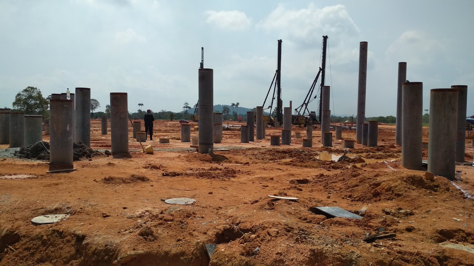
Steps to build a deep foundation (Example of a driven end bearing piles at site).
a. Pegging of pile points at site based on a designed pile point drawing plan.


b. Demobilization of piles at site. A lorry send a group of piles to site and a crane carry out the demobilization work of piles at suitable place near to the pile point.

c. Next, the piling machine started to carry a pile and drove the pile at the pegged point.

2. Diaphragm wall

A diaphragm wall is a structural
concrete wall constructed in a deep trench excavation, either cast in situ or
using precast concrete components. Diaphragms walls are often used on congested
sites, close to existing structures, where there is restricted headroom, or
where the excavation is of a depth that would otherwise require the removal of
much greater volumes of soil to provide stable battered slopes.
Diaphragm walls are suitable for
most subsoils and their installation generates only a small amount of vibration
and noise, which increases their suitability for works carried out close to
existing structures. In addition, floor slab connections and recessed formwork
can be incorporated into the walls.
The walls generally range in
thickness from 500 - 1,500 mm and can be excavated to depths of over 50 m.
Excavation is typically carried out using rope-suspended mechanical or
hydraulically-operated grabs. Specific ground conditions or greater depths may
require the use of hydromills – hydraulically-operated reverse circulation
trench cutters – to penetrate into hard rock by ‘cutting’ rather than
‘digging’. Hydromills can achieve depths of up to 80 m.
The excavation stability is
maintained by the use of a drilling fluid, usually a bentonite slurry. This is
a controlled mixture that has thixotropic properties, meaning that it exerts a
pressure in excess of the earth and hydrostatic pressures on the sides of the
excavation. The walls are constructed, using reinforced or unreinforced
concrete, in discrete panel lengths generally ranging between 2.5 - 7 m. Purpose-made
stop ends can be used to form the joints between adjacent panels, with a water
bar incorporated across the joints. More complicated arrangements such as ‘L’
or ‘T’-shaped panels can be constructed where additional bending moment
capacity or wall stiffness is required.
Precast concrete diaphragm walls
have the same advantages but are less flexible in terms of design. The units
are installed in a trench filled with a special mixture of bentonite and cement
with a retarder added to control the setting time. Ground anchors are used to
tie the panels or posts to the retained earth to provide stability.
The high cost of diaphragm walls can
make them uneconomic unless they can be incorporated into part of a building
structure. As such, they are suited for deep basements, underground car parks
and rail stations, tunnel approaches, underpasses, deep shafts for tunnel
ventilation, pumping stations, and so on.
3. Caisson
A caisson is a box-like structure
commonly used in civil engineering projects where work is being carried out in
areas submerged in water. Such projects might include:
- Bridge piers.
- Abutments in lakes and rivers.
- Break water and other shore protection works.
- Wharves and docks.
- Large water front structures.
Caissons differ from cofferdams in
that cofferdams are removed after completion of the work, whereas caissons are
built to remain in place as a part of the completed structure.
Caissons can be made of materials
including timber, steel, masonry and reinforced concrete, and may be
constructed onshore then floated to the required location, where they are sunk
into place, enabling access to the bed and excavation of foundations to the
required depth.
They are particularly suitable for
the construction of underwater foundations or where the water is deep, as they
are strong enough to withstand significant vertical and horizontal loads, as
well as lateral forces such as waves.
Box caisson
This is a watertight timber or
reinforced concrete box with a closed bottom and an open top. The caisson is
cast and cured on land and then sunk into place, or it can be rested on top of
a pile formation. Sand, concrete or gravel is used to weigh down and sink the
caisson. This is most suitable for areas where the bearing strata is reasonably
level and no excavation is required, although it is possible for some dredging
to further level the base if required to avoid the tilting of the caisson once
in place. This type of caisson is generally relatively economical but may not
be suitable if the bearing strata requires compacting and/or leveling.

Open caisson
This is a timber, steel or concrete
box that is open at both the bottom and the top. The walls are heavy and made
with sharp edges that facilitate the sinking process. There are three different
types of open caisson:
i. Single
wall
ii.
Cylindrical
iii. Open with dredging wells

Example of an open caisson.
Pneumatic caisson
Pneumatic caissons are closed at the
top but open at the bottom, with the water forced out using compressed air,
creating a working chamber which is airtight in order for excavation to be
carried out. This is suitable when it is not possible to excavate wet ground in
the open.
Although this method is suitable for
difficult locations, such as depths ranging from 25-40 m, it is a complex, slow
and expensive procedure.

Selection of Type of
Foundation
The selection of a particular type
of foundation is often based on a number of factors, such as:
1. Adequate depth
The foundation must have an adequate
depth to prevent frost damage. For such foundations as bridge piers, the depth
of the foundation must be sufficient to prevent undermining by scour.
2. Bearing capacity failure
The foundation must be safe against
a bearing capacity failure.
3. Settlement
The foundation must not settle to
such an extent that it damages the structure.
4. Quality
The foundation must be of adequate
quality so that it is not subjected to deterioration, such as from sulfate
attack.
5. Adequate strength
The foundation must be designed with
sufficient strength that it does not fracture or break apart under the applied
superstructure loads. The foundation must also be properly constructed in
conformance with the design specifications.
6. Adverse soil changes
The foundation must be able to
resist long-term adverse soil changes. An example is expansive soil, which
could expand or shrink causing movement of the foundation and damage to the
structure.
7. Seismic forces
The foundation must be able to
support the structure during an earthquake without excessive settlement or
lateral movement.
Based on an analysis of all of the
factors listed above, a specific type of foundation (i.e., shallow versus deep)
would be recommended by the geotechnical engineer.
Foundation Failures
Foundations provide the support and resistance of the loads of the structures above. They serve as structural systems that transfer loads to the soil below and that provide stability, including resistance to overturning, sliding, and uplift, for the overall structure. Due to the importance of their structural system to the overall structure, it is imperative that their structural integrity is maintained for the overall structure to function. However, in some cases, foundations can fail. We are now going to explore the different types of causes that can affect the failure of foundations, in order to prevent and remediate the failures.
Below are the causes of foundation
failures:
Uneven loading
The uneven distribution of loading
from the superstructure can induce uneven stresses at different locations of
the foundation. This can cause differential settlement at locations where
vertical structural elements, such as columns and walls, directly transfer the
superstructure loads to the foundation. Differential settlement can
eventually lead to cracks at the foundation.
Overloading
Overloading from the superstructure
can also create foundation failure. Foundations can fail by cracking when
the design moment and/or shear is above its moment and/or shear capacity.
Failure can also occur when there are large concentrated or point loads, which
can induce large punching shear onto the foundation, and when there is over
designing of bearing pressure.
Different properties of soil at the
foundation interface
Different parts of the foundation
can rest on different properties of soil. For example, one part of the
foundation can sit on clay, while another part of the foundation can sit on
rock. When all design checks are adequate for one part of the foundation due to
that part resting on good soil and when checks fail for another part of the
foundation due to bad soil properties at the other part of the foundation, the
whole foundation can fail.
Ground investigation will need to be
used to determine these different soil properties. The foundation
structure will need to be designed in consideration of the different soil
stiffness and soil properties.
Insufficient soil compaction
The soil fill underneath the
foundation might not be compacted properly and to its required degree of
compaction. Since the soil is not compacted properly, air voids can be created
within the soil, in which soil and water can displace in and out of. There will
then be movement within the soil, which causes swelling and contracting. The
swelling and contraction of the soil can cause pressure to the foundation that
the soil supports.
Air voids within the soil can cause
loose soil or soil with low density, which lacks adequate strength to support
the foundation. Poor compaction equipment can also lead to foundation failure.
Therefore, it is best to compact the
soil beneath the foundation to its required compaction degree before concrete
placement of the foundation, in order to reduce soil displacement, to increase
subgrade reaction and soil density, and to reduce differential and overall
settlement of the foundation.
Uneven moisture levels of soil
beneath the foundation
Similar to the above scenario,
uneven moisture levels of the soil can cause soil swelling and contraction at
specific parts of the foundation. This can lead to stress at intersecting
locations where the soil is swelling and contracting and where the soil is not.
Changes in moisture levels of soil
beneath the foundation
Moisture levels of the soil can change due to varying humidity levels, rainy weather, or poor drainage conditions, which can cause soil to swell (or heave) and contract, therefore leading to cracks. Similar to insufficient soil compaction, the voids within the soil can be filled up by water or other fluids, which can create pressure onto the soil particles from the fluid.
However, when there are dry periods, the water evaporates from the soil and leaves from the voids within the soil. This can cause soil shrinkage.
Moreover, when there are cracks within the foundation, water seepage can also occur.
Vibration from adjacent construction
Vibration from nearby construction can displace soil particles underneath the foundation. This can then create air voids within the soil, which can loosen up the soil and lower the soil density. The lower the soil density, the lower the soil strength for the support of the foundation. This will then cause foundation failure.
Vibration from nearby construction can displace soil particles underneath the foundation. This can then create air voids within the soil, which can loosen up the soil and lower the soil density. The lower the soil density, the lower the soil strength for the support of the foundation. This will then cause foundation failure.
Transpiration
If there are trees adjacent to the foundation, the trees can evaporate the water from the soil into its roots and into the atmosphere. This can cause changes in the moisture level of the soil.
If there are trees adjacent to the foundation, the trees can evaporate the water from the soil into its roots and into the atmosphere. This can cause changes in the moisture level of the soil.
Conclusion
The foundation is the base and one of the most important part in the
construction of any building or structure. Foundation act as a main part to
carry the structure load above of it and transfer the load into the ground to
prevent the structure or building from collapse. The type of foundation must be
wisely chose and designed based on the type of soil at site to maximise its
function. To prevent the case of foundation failure, soil investigation work
must be carry out carefully.


this article is great because of that it contain a great information. and Strip Footing Foundation is a small family run business offering a professional and expert service of piling and groundwork throughout Essex, Hertfordshire and London.
ReplyDeleteContig Wall Piling is a reliable solution for creating robust and durable retaining walls in construction projects. At Alpha Piling LTD, we specialize in delivering high-quality contig wall piling services, ensuring stability and efficiency for your construction needs. Contact us today for expert piling solutions tailored to your requirements."
ReplyDeleteGreat technical report! The explanation of ground anchor systems is thorough and insightful. Bhagwati Machinery appreciates such detailed content that supports civil engineering professionals. Thanks for sharing!
ReplyDelete